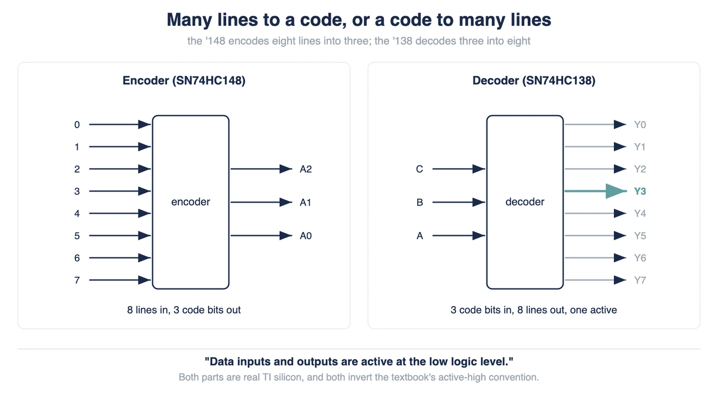
An encoder collapses many input lines into a short binary code. A decoder expands that code back into many output lines. TI’s SN74HC148 devices “encode eight data lines to 3-line (4-2-1) binary (octal)”, and its SN74HC138 reverses that. So the popular one-liner calls a decoder the inverse of an encoder. That answer breaks on the encoder’s own function table. Nothing asserted and input 0 asserted leave the same code on the output pins. Only the GS and EO status pins tell those two states apart. Both parts also run active-low, which changes how every table value reads.
Encoders and decoders sit on opposite sides of one idea. One turns an active line into a number, and the other reverses that. The symmetry is real, though it is not perfect.
This guide reads two Texas Instruments datasheets directly. The SN74HC148 priority encoder and the SN74HC138 decoder are both commodity parts you can still buy. Where the usual comparison tables disagree with those documents, the datasheet wins here.
What Each One Converts
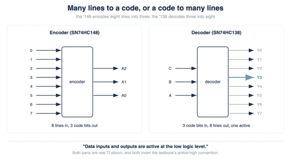
Start with the direction of the conversion, since everything else follows from it. An encoder has many inputs and few outputs. A decoder, conversely, has few inputs and many outputs.
TI states the encoder side plainly. Its SN74HC148 devices “encode eight data lines to 3-line (4-2-1) binary (octal)”. Eight data lines therefore shrink to three code pins.
The decoder side is a mirror of that. On the SN74HC138, “The three input pins, A, B, and C, select which output is active”. Three code pins expand back to eight lines.
Both parts are combinational circuits, so neither one stores anything. Texas Instruments says as much for the encoder, warning that “wrong addresses can appear during input transients”. Our combinational vs sequential circuit guide covers why that distinction matters.
Neither block is exotic, either. Encoders and decoders sit beside adders as basic combinational parts. Our half adder vs full adder guide covers that same family.
Inside a Real Encoder
The part to read is the SN54HC148 and SN74HC148 from Texas Instruments. Its datasheet, document SCLS109H, dates from April 2004, with a March 2022 revision. TI titles it “SNx4HC148 8-Line to 3-Line Priority Encoders”.
Read one sentence before you read any table, or every value will look wrong. TI writes that “Data inputs and outputs are active at the low logic level”. Active-low means a pin does its job when it sits low, rather than high.
A request therefore arrives on this encoder as a low, never as a high. An idle input line, meanwhile, stays high. The three code outputs also come out complemented.
Work one example through, because that complement trips people up. Pull input 7 low and the code pins A2, A1 and A0 all go low. Invert those three lows, so you get 111, which is decimal 7.
Input 0 gives the opposite pattern. Its code pins read high, high, high, which inverts to 000. That single fact sets up the trap in the next section.
The HC148 is not a plain encoder, though, and the word priority earns its place. TI describes “priority decoding of the inputs to ensure that only the highest-order data line is encoded”. Drive three inputs low at once and the highest-numbered one wins.
That ranking is a design decision rather than a detail. A plain encoder instead assumes exactly one active input at a time. Real inputs, such as interrupt lines or keypad rows, refuse to behave that way.
Two more pins handle expansion. Texas Instruments credits the “input enable (EI) and output enable (EO) signals” for that job. They allow “cascading multiple stages without added external circuitry”. The overview calls the result “octal expansion without the need for external circuitry”.
The Case a Plain Encoder Cannot Resolve
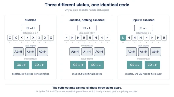
Here is the claim worth testing: a decoder is just an encoder run backwards. The HC148 function table, though, refutes it in two separate ways.
The first problem is collisions. A plain encoder is only defined when exactly one input is active. Two active inputs at once leave the output undefined, which is why the commodity part resolves them by rank.
The second problem survives even if only one input is active. Look at what the code pins do when nothing is asserted at all.
Remember that low means asserted on this part, because the table below is dense with H and L. Three of its rows produce the very same code, and only the status pins separate them.
| EI | Data inputs 0 to 7 | A2 A1 A0 | GS | EO | What the row means |
|---|---|---|---|---|---|
| H | All eight ignored | H H H | H | H | Switched off, so the code means nothing |
| L | All eight high | H H H | H | L | Switched on, though nothing is asserted |
| L | Input 0 low, rest high | H H H | L | H | Input 0 is asserted, since GS reads low |
Those three rows come from Table 8-1 of the SN74HC148 datasheet, with the eight data columns condensed into one. Every code pin therefore reads the same across all three. So the code alone cannot tell you what happened.
GS, however, answers the question the code pins cannot. That pin goes low when an enabled part actually has a request to report. Compare the last two rows and the difference jumps out.
Meanwhile, EO carries the other half of the story. It goes low only when EI sits low and every input stays idle. Chain it into the next stage’s EI and eight-line encoders cascade cleanly.
Still, none of this makes a plain encoder useless. It simply covers one case, the one-hot input. Real silicon then adds priority logic and status flags to cover everything else.
A decoder meets neither problem. Every input code is a legal code, so nothing needs arbitrating. Nothing is ambiguous either, because each of the eight codes owns its own output.
Inside a Real Decoder
The matching part is the SN54HC138 and SN74HC138. Its datasheet, document SCLS107G, goes back to December 1982, with an October 2021 revision. TI titles it “SNx4HC138 3-Line To 8-Line Decoders/Demultiplexers”.
Again, read the polarity note first, then read the table. TI says this device “features three binary inputs to select a single active-low output”. Therefore the active output is the one sitting low.
The overview spells the behaviour out in one line. “The selected output is pulled LOW, while the remaining outputs are all HIGH.” Seven idle pins read high, which looks backwards until you accept the polarity.
Selection itself is simple. “The three input pins, A, B, and C, select which output is active.” Three bits give eight codes, and the part uses all eight.
Three enable pins gate the whole thing. TI provides “Two active-low and one active-high enable inputs” on purpose. They “reduce the requirement for external gates or inverters when expanding”.
The payoff is concrete. “A 24-line decoder can be implemented without external inverters, and a 32-line decoder requires only one inverter.”
Now for a claim that needs a boundary drawn around it. Textbooks generally say a decoder activates exactly one output. For the HC138 that holds, and TI leans on it in an application note. The part “ensures that no more than one output is pulled to a low-level logic voltage”.
Two limits apply, though. Disable the part, and then no output is active at all. TI is explicit here, since “any enable pin can be deactivated to force all outputs high”. In fact, three of the eleven rows in its function table do exactly that.
The second limit is the bigger one. One-of-N decoders behave that way, while other decoders do not. TI’s CD74HC4511 is a BCD-to-seven-segment part, and its job is lighting several segments at once. Document SCHS279E calls the family “BCD-to-7 segment latch/decoder/drivers”.
Its function table settles the point. Feed the code for the digit 8, and all seven outputs drive high together. The code for 0 drives six outputs high, while output g stays low. That is a decoder lighting many outputs at once, by design.
So state the rule with its scope attached. A one-of-N decoder activates exactly one output while its enables all hold. A display decoder maps each code to a pattern instead.
Encoder vs Decoder: Comparison Table
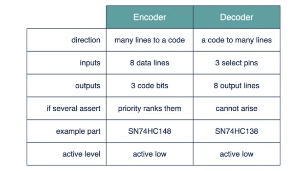
The table below sets the two blocks against each other, row by row. Every value traces back to the TI datasheets named above.
| Aspect | Encoder (SN74HC148) | Decoder (SN74HC138) |
|---|---|---|
| Direction of conversion | Many active lines down to a binary code | A binary code back out to many lines instead |
| Inputs on the real part | Eight data lines, plus the EI enable | Three select pins as well as three enables |
| Outputs on the real part | Three code pins, though GS and EO join them | Eight output lines |
| What the inputs mean | Which line is asking for service | Which line to select, because the code names it |
| What the outputs mean | The number of the asking line | Which single line is active, while the rest idle |
| Inputs normally active at once | One, since the plain form assumes one-hot | All three select pins, since a code needs every bit |
| Outputs normally active at once | One code, though it can be ambiguous | Exactly one, while the enables hold |
| On several active inputs | Undefined, unless the part ranks them | Cannot arise, since three pins only ever carry one code |
| How the real part settles that | “priority decoding of the inputs”, so rank wins | Nothing to settle, since every code is legal |
| Status outputs | GS and EO, because three rows share one code | None, since no code is ambiguous |
| Enable pins | EI going in, EO coming out | “Two active-low and one active-high enable inputs” |
| Expansion approach | “octal expansion without the need for external circuitry” | “A 24-line decoder can be implemented without external inverters” |
| TI’s own title | “8-Line to 3-Line Priority Encoders” | “3-Line To 8-Line Decoders/Demultiplexers” |
| Datasheet document | SCLS109H, revised March 2022 | SCLS107G, revised October 2021 |
| Active level in silicon | “Data inputs and outputs are active at the low logic level” | “a single active-low output” |
| Reading the code | Complemented, so invert before reading | Straight off the select pins instead |
| Demultiplexer role | None, since TI ships it purely as an encoder | The same die, since TI calls them “3-to-8 decoders and demultiplexers” |
| Typical propagation delay | “Typical tpd = 16ns” | “Typical tpd = 15 ns” |
| Applications TI lists | “N-Bit encoding”, “Code converters and generators” | “LED Displays”, “Servers”, “Factory Automation” |
| Where it sits in a system | Ahead of a narrow bus, ranking requests | “high-performance memory-decoding or data-routing” |
| Combinational or sequential | Combinational, because nothing is stored | Combinational too, since it stores nothing |
One row carries most of the argument: the row for several active inputs. An encoder needs a rule there, whereas a decoder needs nothing. That asymmetry is why the inverse story breaks.
Decoder or Demultiplexer
Ask whether a decoder and a demultiplexer are the same thing and you get two confident, opposite answers. The datasheet gives a better one.
Start with the title on the front page: “SNx4HC138 3-Line To 8-Line Decoders/Demultiplexers”. TI describes the parts as “3-to-8 decoders and demultiplexers”. One piece of silicon, then, carries both names.
The difference lives in how you use the pins. TI is direct about it: “An enable input can be used as a data input for demultiplexing applications.” Hold the enables steady and the part decodes. Feed data into an enable, though, and the same part routes it.
In short, the roles differ, while the hardware does not. A decoder answers which line, whereas a demultiplexer answers which line gets this data. Our multiplexer vs demultiplexer guide covers the routing side in detail.
Two careless answers are worth avoiding here. Calling the pair identical ignores the enable pin’s second job. Saying they are unrelated ignores TI’s own product title.
Why the Real Parts Are Active-Low
Textbook diagrams almost always draw encoders and decoders active-high. A one on an input means asserted, and a one on an output means selected. Real parts, however, often invert both conventions.
Both chips here do exactly that. The HC148 datasheet says “Data inputs and outputs are active at the low logic level”. Likewise, the HC138 datasheet promises “a single active-low output”.
As a result, a student who reads a textbook and then a datasheet meets two different tables. Neither table is wrong. They simply use opposite polarity conventions.
Translating between them takes one habit. Read the pin label first, then decide what low means there. On the HC148, a low input is a request, while a low output bit is a one.
Active-low outputs are not an accident, either. For example, TI’s application section uses the HC138 as “a scanning column selector for an LED Matrix display”. The part supplies “the low side drive of the LED string”, so a low output is the useful one.
One caution belongs here. TI marks that application section as material that “is not part of the TI component specification”. Function tables carry the guarantees, whereas application text carries the ideas.
Where Each One Actually Shows Up
TI lists applications for both parts, and the two lists barely overlap. Start with the encoder.
The HC148 datasheet names “N-Bit encoding” plus “Code converters and generators”. Both jobs share one shape. Many lines arrive, and a short number leaves.
Priority is what makes that shape usable. Several devices can raise a request line simultaneously. The encoder then ranks them, and the highest-numbered request wins.
The HC138 list runs longer and more concrete. Texas Instruments names “LED Displays”, “Servers”, “Power Infrastructure” and “Factory Automation” among others. Its description targets “high-performance memory-decoding or data-routing applications”.
Memory decoding is the classic case. Three address bits pick one of eight chips, so only the selected chip answers. Instruction decoding inside a CPU follows a similar shape, as our hardwired vs micro-programmed control guide explains.
Neither part remembers anything between codes. Add a register and the behaviour changes completely, which is the sequential world our latch vs flip-flops guide covers. Decoders and encoders stay purely combinational.
Which One You Need
The choice is rarely a judgement call, because the wiring decides it. Count the lines on each side.
Many signal lines feeding a narrow bus call for an encoder. Keypad rows, interrupt requests and sensor flags all fit that shape. Add priority when two of them can fire together.
A narrow code feeding many targets calls for a decoder. Address lines picking one memory chip fit that shape exactly. Use the enable pins when you need every output parked.
Finally, one more question settles the demultiplexer case. Ask whether you are routing data or merely selecting a line. Routing data means feeding an enable pin, so the same HC138 does the work.
Interview Questions
Frequently Asked Questions
Wrapping Up
The two blocks answer opposite questions. An encoder asks which line is asking, while a decoder asks which line to pick. Reading them as exact inverses is where the trouble begins.
Keep three facts from the datasheets. Real parts run active-low. A plain encoder also needs status pins to stay unambiguous.
One HC138 die then serves as a demultiplexer too. Those three points answer nearly every exam question on this topic.
Related reading on DiffStudy:
- Multiplexer vs Demultiplexer
- Combinational vs Sequential Circuit
- Half Adder vs Full Adder
- Latch vs Flip-Flops
- Hardwired vs Micro-Programmed Control