2D transformation uses a 3×3 matrix. 3D transformation uses a 4×4 matrix instead. Both rely on one added coordinate. So a 2D point becomes (x, y, 1). A 3D point becomes (x, y, z, 1). That extra coordinate lets translation work as a matrix multiply. 2D has only one rotation matrix, since every 2D rotation shares the same axis. 3D needs three separate ones, Rx, Ry, and Rz. Because the axes differ, order now changes the result. Rotate (1, 2, 3) by 90° around Z then X, and it lands at (−2, −3, 1). Reverse that order, X then Z, and it lands at (3, 1, 2). 2D rotations never behave that way; they always commute. This guide uses column vectors, so a matrix multiplies a point directly, as P′ = M · P.
A 2D scene stays flat, while a 3D scene has real depth. So every renderer needs a rule for moving points through either one. That rule is a transformation, and it always comes down to a matrix.
This guide compares 2D vs 3D transformation directly, matrix by matrix. One convention and two worked examples carry the whole comparison, so every number below traces back to them.
Why Transformations Use Matrices
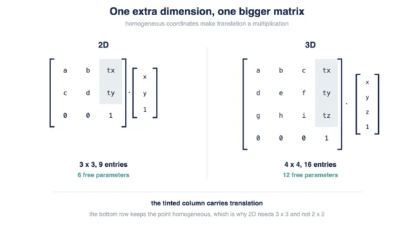
A 2D point needs a third number before any matrix can move it. So it becomes (x, y, 1), not just (x, y). That third number is a homogeneous coordinate.
The extra coordinate exists for one reason. It lets translation become a matrix multiply, instead of a separate addition step. Otherwise, only rotation and scaling could multiply cleanly.
That is also why 2D already needs a 3×3 matrix, not 2×2. A 3D point follows the same logic, one dimension further. It becomes (x, y, z, 1), so 3D transforms need a 4×4 matrix.
One convention matters before any matrix appears below. Points here are column vectors. A matrix sits on the left, so P′ = M · P. In a chain, the rightmost matrix applies first, closest to the point. Some textbooks use row vectors instead; under that convention every matrix transposes, and the multiply order reverses.
Matrices also answer two different questions: moving the object, or moving the axes around it. Our geometric vs coordinate transformation guide covers that split in full. This article instead compares 2D against 3D directly, size for size.
2D Transformations
2D transformation covers three basic moves: translate, scale, and rotate. Each one is a 3×3 matrix, built around the (x, y, 1) point.
Translation shifts a point by (tx, ty). The last column carries that shift, so multiplying by the matrix adds it directly.
T(tx, ty) =
[ 1   0   tx ]
[ 0   1   ty ]
[ 0   0   1  ]
Scaling multiplies x by sx and y by sy. Both factors sit on the diagonal, while everything else stays zero.
S(sx, sy) =
[ sx  0   0  ]
[ 0   sy  0  ]
[ 0   0   1  ]
Rotation turns a point by angle θ. Only one such matrix exists in 2D, since only one axis is available: the implicit axis coming straight out of the page.
R(θ) =
[  cosθ  −sinθ    0   ]
[  sinθ   cosθ    0   ]
[   0      0      1   ]
Still, every 2D rotation shares that single axis. So two rotations always combine by simple addition: R(30°) then R(45°) equals R(75°), in either order.
3D Transformations
3D transformation adds a z-axis, so the point becomes (x, y, z, 1). Every matrix grows to 4×4 to match it.
Translation and scaling extend the same way as 2D, just with one more row and column. Rotation does not extend so simply.
3D offers three separate axes to rotate around: x, y, and z. So three distinct rotation matrices exist, not one.
Rx(θ) rotates around the x-axis. It leaves x unchanged, while y and z rotate between themselves.
Rx(θ) =
[   1      0      0      0   ]
[   0     cosθ  −sinθ    0   ]
[   0     sinθ   cosθ    0   ]
[   0      0      0      1   ]
Ry(θ) rotates around the y-axis. Its sign pattern looks different from the other two: +sinθ sits in the top right, not −sinθ. That is not a mistake. It follows from the right-handed axis order, and every Ry matrix keeps that pattern.
Ry(θ) =
[  cosθ    0     sinθ    0   ]
[   0      1      0      0   ]
[ −sinθ    0     cosθ    0   ]
[   0      0      0      1   ]
Rz(θ) rotates around the z-axis. It mirrors 2D rotation closely, since it only touches x and y.
Rz(θ) =
[  cosθ  −sinθ    0      0   ]
[  sinθ   cosθ    0      0   ]
[   0      0      1      0   ]
[   0      0      0      1   ]
Overall, all three matrices stay orthogonal, with determinant +1. So each one is a genuine rotation, never a reflection hiding inside.
2D vs 3D Transformation: Comparison Table
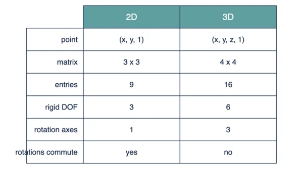
In particular, the table below lines up 2D against 3D transformation, field by field.
| Aspect | 2D Transformation | 3D Transformation |
|---|---|---|
| Point tuple | (x, y, 1) | (x, y, z, 1) |
| Matrix size | 3×3 | 4×4 |
| Matrix entries | 9 | 16 |
| Free affine parameters | 6 | 12 |
| Rigid-body degrees of freedom | 3 (2 translate + 1 rotate) | 6 (3 translate + 3 rotate) |
| Rotation axes | 1, implicit | 3, x/y/z |
| Distinct rotation matrices | 1, R(θ) | 3, Rx/Ry/Rz |
| Shear parameters | 2 | 6 |
| Do rotations commute | Yes, always | No, order changes the result |
| Does operation order matter | Yes, even translate vs scale | Yes, and more visibly so |
| Translation mechanism | Matrix multiply, via homogeneous coordinate | Matrix multiply, same mechanism |
| Scaling parameters | sx, sy | sx, sy, sz |
| Reflection | Negative sx or sy | Negative sx, sy, or sz |
| Projection needed for a screen | No, already planar | Yes, a separate step |
| Typical uses | UI, icons, sprites, vector art | Games, CAD, simulation, VR/AR |
| Homogeneous coordinate | 3rd value, the 1 in (x, y, 1) | 4th value, the 1 in (x, y, z, 1) |
Indeed, one pattern threads through this table. Most 3D numbers roughly double their 2D counterpart, except rotation matrices, which triple instead. That tripling comes from the extra axis, never from a general doubling rule.
Why the Matrix Grows from 3×3 to 4×4
3×3 becomes 4×4 for the same reason 2×2 never worked in 2D. Every matrix needs one extra row and column for the homogeneous coordinate, not simply one row per dimension.
So entries jump from 9 to 16, not from 4 to 9. Likewise, free affine parameters jump from 6 to 12. In the same way, rigid-body degrees of freedom jump from 3 to 6, three for translation and three for rotation.
Rotation grows the fastest of all. 2D uses one rotation matrix; 3D needs three, one per axis. Shear grows too, from 2 parameters to 6, since each axis can now lean toward two others.
None of this comes from simply adding a z-axis on top, though. It comes from the homogeneous coordinate, doing the same job it always did, just one dimension larger.
Worked Example: The Same Point, Two Orders
Point P = (2, 3) shows how order changes a result, even in plain 2D.
| Order | Result |
|---|---|
| Translate by (4, 5), then scale by (2, 2) | (12, 16) |
| Scale by (2, 2), then translate by (4, 5) | (8, 11) |
Translate first, and P moves to (6, 8). Scale that by (2, 2), and it lands at (12, 16).
Scale first instead, and P moves to (4, 6). Translate that by (4, 5), and it lands at (8, 11).
Same two operations, same starting point, different order, different answer. So order already matters in 2D, well before rotation enters the picture.
Why 3D Rotation Order Changes the Result
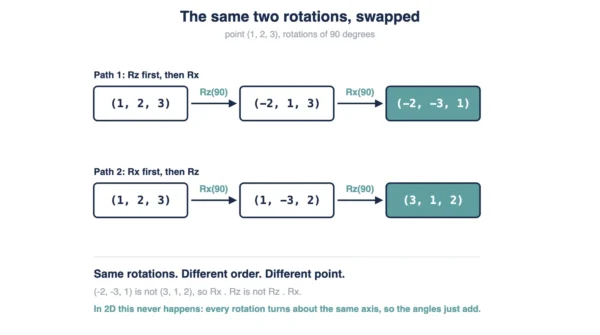
3D rotation makes the same order problem far more visible. Point P = (1, 2, 3), rotated 90° twice, tells the story.
| Step | Path 1: Z then X | Path 2: X then Z |
|---|---|---|
| Start | (1, 2, 3) | (1, 2, 3) |
| After first rotation | (−2, 1, 3) | (1, −3, 2) |
| After second rotation | (−2, −3, 1) | (3, 1, 2) |
Path 1 rotates around Z first, then around X. Path 2 reverses that order, X, then Z.
The two paths land at different points: (−2, −3, 1) against (3, 1, 2). The matrix products differ too, since Rx·Rz does not equal Rz·Rx.
2D rotation never does this. R(30°) then R(45°) always equals R(45°) then R(30°), and both equal R(75°). Every 2D rotation shares one axis, so the angles simply add.
3D rotations turn around different axes instead. So combining them depends on axis order, not just on the two angles involved. That gap, order changing the outcome, is the deepest difference between 2D and 3D transformation, well beyond any size difference in the table above.
Getting 3D Back onto a 2D Screen
3D transformation still leaves a point sitting in 3D. Getting it onto a flat screen needs one more step: projection.
Projection is not a fourth transformation next to translate, scale, and rotate. Instead, it runs after them, mapping a 3D point down to 2D.
Two projection styles exist, parallel and perspective. Our perspective vs parallel transformation guide covers that difference in full, so this article will not repeat it here.
Projection is only one stage of a longer pipeline, though. Our viewports and viewing transformations guide walks through the stages around it.
Where Each One Shows Up
2D transformation covers flat work: user interfaces, icons, sprites, and vector art. None of that work ever needs a third axis.
3D transformation covers anything with real depth: games, CAD models, physical simulation, and VR or AR scenes. All of it needs the extra axis, plus the rotation order that comes with it.
Both eventually reach a screen, which stays 2D either way. Before that happens, geometry outside the view gets trimmed away. Our windowing vs clipping guide covers that trimming step.
The window and the viewport are not the same thing, either. Our viewport vs window guide untangles that mapping.
Interview Questions
Frequently Asked Questions
Wrapping Up
2D and 3D transformation both start from the same trick: one extra coordinate, so translation becomes a multiply. From there, the two diverge quickly. 2D stays at 3×3, with one rotation axis that always commutes.
3D grows to 4×4, with three rotation axes that do not commute. That single fact, order changing the result, matters more than any size difference between the matrices themselves.
Remember the essentials before an exam or an interview. Points are column vectors, multiplied as P′ = M · P. Ry alone flips its sign pattern, and that is not an error. Projection stays a separate step, never one of the transformations itself.
Related reading on DiffStudy:
- Geometric vs Coordinate Transformation
- Perspective vs Parallel Transformation
- Viewports and Viewing Transformations
- Windowing vs Clipping
- Viewport vs Window