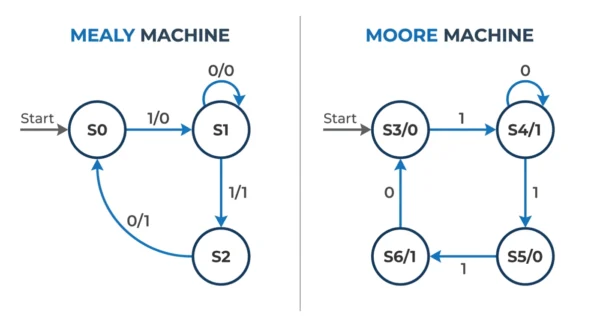
A Mealy machine produces its output from both the current state and the current input, so the output is written on the transitions and can change the moment the input changes. A Moore machine produces its output from the current state alone, so the output is written inside each state and only changes after a state transition. Mealy machines react one clock earlier and usually need fewer states; Moore machines have steadier, glitch-resistant outputs that are easier to design.
Mealy and Moore machines are the two classic models of a finite state machine that produces output — the building blocks behind sequence detectors, vending machines, traffic controllers and almost every digital control circuit. They recognise the same problems and store the same state. The single thing that separates them is what the output depends on.
In a Mealy machine the output is a function of the state and the input together. In a Moore machine the output is a function of the state only. That one difference changes how the state diagram is drawn, how many states you need, how fast the output reacts, and how prone the circuit is to glitches.
This guide builds both models from their formal definitions, walks through the same 101 sequence detector designed each way, shows how to convert between them, and covers the timing, applications and exam points that come up most often.
Finite State Machines in Brief
A finite state machine, or FSM, is a model with a finite set of states, a defined start state, and rules that move it from one state to another as it reads input. Mealy and Moore machines are the two FSMs that also produce output, which is why they are called transducers. They differ from the DFA and NFA, which only accept or reject a string rather than emit an output symbol at each step.
In hardware terms, both are sequential circuits: a block of memory (flip-flops) holds the state, and a block of combinational logic computes the next state and the output. The only structural question is whether the output logic reads just the state register, or the state register and the input together.
The Mealy Machine
A Mealy machine produces output from the current state and the current input. Because the input takes part in the output, the output is attached to the transitions of the state diagram and is written in input / output form on each arrow.
Formally, a Mealy machine is a six-tuple (Q, q0, Σ, O, δ, λ):
Q— a finite set of statesq0— the start stateΣ— the input alphabetO— the output alphabetδ: Q × Σ → Q— the next-state (transition) functionλ: Q × Σ → O— the output function, which reads state and input
The output function is the defining feature: λ takes both arguments. A classic example is a vending machine that releases a product the instant the final coin is inserted — the action depends on the running total (state) and the coin just added (input), not on waiting for the next clock tick.
Advantages
- Fewer states — often needs fewer states than a Moore machine for the same task.
- Faster response — output reacts in the same cycle as the input, one step ahead of Moore.
- Fine-grained output — different inputs from one state can give different outputs.
Disadvantages
- Glitch-prone — output can change asynchronously with the input, so input noise can ripple through.
- Harder to design — transition-based output is trickier to reason about and debug.
- Timing-sensitive — output is not registered, so it must be sampled carefully.
The Moore Machine
A Moore machine produces output from the current state alone. The input has no direct part in the output, so the output is attached to the states and is written inside each node in state / output form. The output stays constant for as long as the machine sits in a state and changes only when it moves to a new one.
Formally, a Moore machine is also a six-tuple (Q, q0, Σ, O, δ, λ), and only the output function differs:
δ: Q × Σ → Q— the next-state function, same as Mealyλ: Q → O— the output function, which reads the state only
A traffic-light controller is the textbook example: the lights shown depend purely on which state the controller is in (green, yellow or red), and they change only when the controller transitions to the next state on a timer.
Advantages
- Stable, glitch-free output — output changes only on a state transition, synchronised to the clock.
- Easier to design — one output value per state is simple to reason about and verify.
- Safer in synchronous systems — predictable timing makes it the default for clocked control logic.
Disadvantages
- More states — often needs an extra state per distinct output value.
- One cycle slower — output appears a clock tick after the input that caused it.
- Less granular — a single state cannot give two different outputs for two inputs.
Worked Example: A 101 Sequence Detector
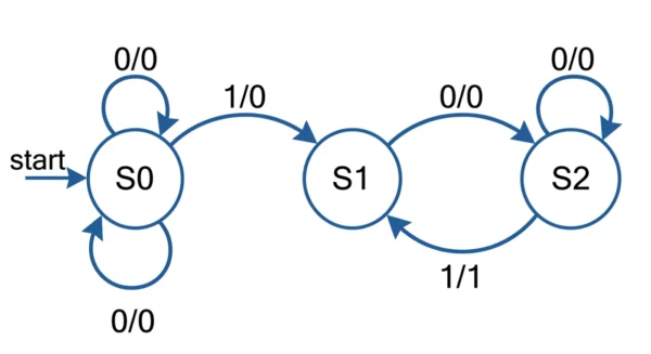
The clearest way to see the difference is to build the same circuit both ways: a detector that outputs 1 whenever it has just seen the pattern 101 in a bit stream (overlapping matches allowed). The Mealy design needs three states; the Moore design needs four. That extra state is the price Moore pays for tying output to states.
Mealy version (three states)
Output is shown as part of each transition. Detection happens on the arrow leaving S2 on input 1.
| Present state | Input = 0 (next state / output) | Input = 1 (next state / output) |
|---|---|---|
| S0 — no useful prefix | S0 / 0 | S1 / 0 |
| S1 — seen “1” | S2 / 0 | S1 / 0 |
| S2 — seen “10” | S0 / 0 | S1 / 1 |
Moore version (four states)
Output belongs to the state. A dedicated state S3 carries output 1 to signal a match.
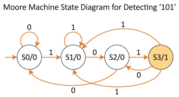
| Present state | State output | Next state (input = 0) | Next state (input = 1) |
|---|---|---|---|
| S0 — no useful prefix | 0 | S0 | S1 |
| S1 — seen “1” | 0 | S2 | S1 |
| S2 — seen “10” | 0 | S0 | S3 |
| S3 — seen “101” | 1 | S2 | S1 |
Feed both machines the stream 1 0 1 0 1. The Mealy detector raises its output during the third bit, the moment the second 1 arrives. The Moore detector raises its output on the next clock edge, once it has settled into state S3. Same detections, one cycle apart — that timing offset is the practical heart of the Mealy versus Moore choice.
Converting Between the Two
The two models are equivalent in power: any Mealy machine can be rewritten as a Moore machine and vice versa. Only the state count and output timing change.
Moore to Mealy
Always straightforward and never adds states. Move each state’s output onto every transition that enters that state. The result has the same number of states and reacts one cycle earlier.
Mealy to Moore
May add states. If a Mealy state can be reached by transitions carrying different outputs, split it into one copy per distinct output value so each new state has a single, well-defined output. This is why Moore versions are usually larger.
Mealy vs Moore Machines: Key Differences
| Aspect | Mealy Machine | Moore Machine |
|---|---|---|
| Output depends on | Current state and current input | Current state only |
| Output function | λ: Q × Σ → O | λ: Q → O |
| Output shown on | Transitions (input / output on the arrow) | States (state / output inside the node) |
| Number of states | Usually fewer | Usually more (often one extra per output value) |
| Output timing | Reacts in the same cycle as the input | Reacts one clock cycle later |
| Output stability | Can change asynchronously, more glitch-prone | Changes only on state transition, glitch-resistant |
| Design effort | Harder to design and debug | Easier to design and verify |
| Best suited to | Fast reaction, fine-grained control | Stable, predictable, synchronous output |
| Typical examples | Vending machines, protocol controllers, signal processing | Traffic lights, elevators, digital clocks |
Output Timing and Glitches
The timing difference is the reason the choice matters in real hardware. A Moore output is driven straight from the state register, so it is effectively registered and changes cleanly on the clock edge. That makes it the safe default in synchronous designs where downstream logic samples the output on the same clock.
A Mealy output is combinational logic of the input, so it can change part-way through a clock cycle and can briefly glitch if the input is noisy. The upside is speed: the Mealy output is available a full cycle earlier. A common engineering compromise is to take a Mealy design and pass its output through a flip-flop, which buys the smaller state count while restoring clean, registered timing.
Applications
Where Mealy fits
- Vending and ticketing machines that act the instant a coin lands
- Communication and bus protocol controllers
- Signal-processing blocks needing immediate response
- Pattern and sequence detectors where state count matters
Where Moore fits
- Traffic-light and crossing controllers
- Elevator and lift control systems
- Digital clocks and timers
- Any control unit where output stability beats raw speed
GATE Exam Tips
- Count states carefully. A frequent question asks for the minimum states in a Moore versus a Mealy sequence detector. The Moore version typically needs one more state to hold the output.
- Know the output functions cold. Mealy is
λ(state, input); Moore isλ(state). That single line answers most theory questions. - Remember the timing. For the same input, the Mealy output leads the Moore output by one clock cycle.
- Diagram convention. Output on the arrow means Mealy; output in the circle means Moore.
- Equivalence. Both accept the same languages and can be converted to each other — conversion never changes computational power, only state count and timing.
Frequently Asked Questions
Wrapping Up
Mealy and Moore machines solve the same problems and store the same state. The fork is whether output reads the input alongside the state, or the state alone. That choice decides how the diagram is drawn, how many states you need, and whether the output reacts this cycle or the next.
Reach for a Mealy machine when reaction speed and a tight state count matter, and for a Moore machine when steady, glitch-free output and easy verification matter more. If you remember one line, make it this: output on the transition is Mealy, output in the state is Moore.
Related reading on DiffStudy:
- DFA vs NFA — the finite automata that accept languages rather than emit output
- Combinational vs Sequential Circuits — the circuit family that finite state machines belong to
- Latch vs Flip-Flops — the elements that store an FSM’s state
- Synchronous vs Asynchronous Transmission — the timing model behind Moore and Mealy outputs
- Half Adder vs Full Adder — more foundational digital-logic building blocks