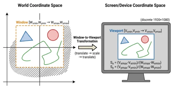
Viewport vs Window in Computer Graphics is one of the most foundational concepts in rendering — and one of the most frequently confused, because “window” in graphics means something completely different from an OS window, and “viewport” in CSS means something slightly different from viewport in OpenGL. Getting this clear unlocks how every 2D and 3D rendering pipeline works: from CAD tools zooming and panning a technical drawing, to a game engine rendering split-screen multiplayer, to a web browser converting CSS coordinates to physical pixels. The window is a rectangle you define in world coordinate space — it selects which region of your mathematical scene to show. The viewport is a rectangle you define in screen or device coordinate space — it controls where on the physical display that selection appears. The pipeline connecting them — select, clip, transform — is the same whether you’re writing raw OpenGL, building a game in Unity, or implementing a 2D graphics library from scratch.
Why Viewport vs Window in Computer Graphics Matters
Every 2D and 3D rendering system — OpenGL, WebGL, DirectX, game engines, CAD tools, SVG renderers, data visualisation libraries — implements the window-viewport model whether it names it explicitly or not. When you call glViewport() in OpenGL, you are setting the viewport. When you zoom into a map in Google Maps, the map tile server is responding to a change in the window. When a game renders split-screen, it maps one world window to two viewports. When a browser converts vw and vh CSS units to pixels, it is referencing the viewport in the graphics sense.
The confusion arises from terminology collision. The word “window” in everyday computing means an OS window — a draggable, resizable application frame. In computer graphics, “window” means something orthogonal: a rectangular region in the mathematical coordinate space of your scene. These two uses of the word coexist, and context determines which is meant. The graphics window and the OS window can be the same size, but they describe different things: one is in world space, the other is in pixel space.
The Window: Selecting What to Show
In computer graphics, the window (also called the world window or viewing window) is a rectangular region defined in world coordinate space — the abstract mathematical space where your scene exists. World coordinates have no inherent connection to pixels or displays. A CAD drawing might use millimetres; a map application might use latitude and longitude; a game might use arbitrary units where 1 unit equals 1 metre. The window is a rectangle you define within that space, specified by its minimum and maximum corners:
Window boundary:
  (Wxmin, Wymin)  ←  bottom-left corner in world coordinates
  (Wxmax, Wymax)  ←  top-right corner in world coordinates
Everything inside the window will be visible in the final rendered image. Everything outside will be clipped — discarded from the rendering pipeline before reaching the screen. The window is your camera frame placed in the world.
What the Window Controls
- Panning: Translating the window — moving both Wxmin/Wxmax and Wymin/Wymax by the same amount — shifts the viewable region without changing zoom level. The scene moves relative to the display
- Zooming in: Making the window smaller (reducing Wxmax−Wxmin and Wymax−Wymin) while keeping the viewport the same size causes the same viewport to display a smaller world-space region — which appears as zoom-in because the same viewport pixels now represent fewer world units
- Zooming out: Enlarging the window shows a larger region of the world in the same viewport area — objects appear smaller because each pixel represents more world-space distance
- Field of view: In 2D graphics, the window width and height directly determine the field of view. In 3D, the near clipping plane and projection parameters extend this concept
- Aspect ratio: The window’s width-to-height ratio determines the shape of the selected region. If the window and viewport have different aspect ratios, the image will appear stretched or compressed unless aspect correction is applied
Window Properties
- Coordinate space: World coordinates — units are defined by the application (pixels, metres, game units, map degrees)
- Size relationship to display: No direct relationship to screen pixels. A world window of width 1000 could map to a 200-pixel viewport or a 1920-pixel viewport — the viewport controls display size
- Clipping authority: The window boundary is the clipping boundary. Any primitive (line, polygon, circle) that intersects the window boundary is clipped before passing to the viewport stage
- Multiple windows: A system can define multiple windows — for example, a minimap and a main view are both windows into the same world coordinate space, each selecting a different region
- Infinite world, finite window: The world coordinate space can be conceptually infinite. The window is a finite aperture through which the system selects a rendering region
Practical examples of window manipulation:
In Google Maps, the visible map boundary is the window — drag the map to pan the window, scroll to resize it. In AutoCAD, the “Zoom Window” command defines a new window boundary; the viewport (your screen) stays the same. In a 2D game, the camera position defines the window centre; moving the camera pans the window. In a graph plotting library, the x-axis and y-axis ranges you set define the window; the plot area on screen is the viewport.
The Viewport: Defining Where to Show It
The viewport is a rectangular region defined in screen coordinate space — the actual pixel grid of your display or rendering target. Unlike the world window, which exists in abstract mathematical space, the viewport is measured in real pixels and has a direct relationship to what appears on the physical screen. It is specified by pixel coordinates:
Viewport boundary:
  (Vxmin, Vymin)  ←  bottom-left corner in screen/pixel coordinates
  (Vxmax, Vymax)  ←  top-right corner in screen/pixel coordinates

OpenGL example:
  glViewport(0, 0, 1920, 1080);
  // Maps the NDC space to the full 1920×1080 screen area
The viewport does not have to fill the entire screen. You can place a viewport anywhere within the display surface — top-left quadrant, a small rectangle in the corner, or anywhere else. Multiple viewports can coexist on the same screen simultaneously, each independently receiving the output of a different rendering pass, or each receiving the same scene rendered from a different camera or at a different scale.
What the Viewport Controls
- Output position on screen: Changing Vxmin and Vymin moves where the rendered output appears on the display — same world content, different screen location
- Output display size: The width and height of the viewport in pixels directly determine how large the rendered image appears on screen. A wider viewport stretches the rendered content to fill more pixels
- Split-screen rendering: Multiple viewports on the same display canvas — each occupying a non-overlapping region — enable split-screen layouts. Each viewport can receive a different render pass
- Picture-in-picture: A small viewport overlaid in the corner of a larger one — used for minimaps, rear-view mirrors in driving games, and preview panels in creative tools
- Letterboxing and pillarboxing: Intentionally leaving regions of the screen outside any viewport — creating black bars above/below (letterbox) or beside (pillarbox) the rendered content when aspect ratios mismatch
Viewport Properties
- Coordinate space: Screen or device coordinates — always in pixels (or device-independent pixels on HiDPI displays)
- Origin convention: OpenGL places the viewport origin at the bottom-left (y increases upward). Most screen-space systems (CSS, HTML5 Canvas, Windows GDI) place the origin at the top-left (y increases downward) — a frequent source of coordinate-flip bugs
- Hardware dependency: The viewport is bounded by the actual resolution of the rendering surface (framebuffer, canvas, or display). You cannot define a viewport larger than the rendering target
- Aspect ratio: The pixel width divided by pixel height of the viewport determines the displayed aspect ratio. If this differs from the window’s aspect ratio, the output will be distorted unless compensated
- Independent of scene: Changing the viewport does not change what part of the world is selected — only where and how large the selected content appears on screen
Viewport in common APIs:
OpenGL: glViewport(x, y, width, height) — sets the screen rectangle receiving the render output; y is from bottom-left. WebGL: gl.viewport(x, y, width, height) — same semantics as OpenGL. CSS: vw and vh units reference the browser viewport dimensions in device-independent pixels. HTML5 Canvas: The canvas element’s width and height define the rendering viewport. Unity: Camera.pixelRect defines the viewport rectangle for each camera. SVG: The viewBox attribute defines the window; the width and height attributes define the viewport.
The Window-to-Viewport Pipeline
The full pipeline from scene geometry to displayed pixels involves four sequential stages. Understanding each stage makes it clear why both the window and viewport are necessary abstractions — collapsing them into a single concept would break every operation that the separation enables.
Stage 1 — World Coordinate Space
Your scene exists as geometric primitives — points, lines, polygons, curves — defined in world coordinates. This space has no pixel dimensions. A polygon might have vertices at (100.5, 230.7) or (−4.2, 17.8) — whatever units the application defines. All modelling, physics, and game logic happens in world space. The rendering pipeline receives this geometry and must ultimately convert it to pixel values on a display.
Stage 2 — Window Selection
The window rectangle (Wxmin, Wymin, Wxmax, Wymax) is applied to world space. Primitives entirely inside the window boundary pass to the next stage unchanged. Primitives entirely outside the window are discarded. Primitives that straddle the boundary are clipped — their vertices are recomputed to produce a new shape that lies exactly on the window’s edge, ensuring no rendering artefacts at the boundary.
Stage 3 — Clipping
Clipping algorithms compute exactly which portions of each primitive lie within the window. For lines, the Cohen-Sutherland and Liang-Barsky algorithms are standard. For polygons, the Sutherland-Hodgman algorithm clips against each window edge in sequence. The output of clipping is a set of primitives that lie entirely within (or exactly on the boundary of) the window — safe to pass to the viewport transformation without producing out-of-bounds pixel writes.
Stage 4 — Window-to-Viewport Transformation
Clipped world-coordinate geometry is mapped to viewport pixel coordinates using the window-to-viewport transformation — a combination of translation and scaling. Every point (Px, Py) inside the window maps to a corresponding point (Vx, Vy) inside the viewport, preserving relative position. A point at the exact centre of the window maps to the exact centre of the viewport. A point at the window’s bottom-left corner maps to the viewport’s bottom-left corner.
The Complete Pipeline at a Glance
| Stage | Input | Operation | Output |
|---|---|---|---|
| 1. World space | Scene geometry in world coordinates | Model + view transforms | Geometry positioned in world space |
| 2. Window selection | World-space geometry | Apply window rectangle | Identify visible vs. invisible primitives |
| 3. Clipping | All primitives | Cohen-Sutherland / Sutherland-Hodgman | Only geometry within window boundary |
| 4. W-to-V transform | Clipped world coordinates | Scale + translate to viewport | Screen pixel coordinates |
| 5. Rasterisation | Screen-space geometry | Scan conversion, shading | Pixel colour values in framebuffer |
The Transformation: Derivation and Formula
The window-to-viewport transformation maps every point in world-coordinate window space to a corresponding point in screen-coordinate viewport space. The mapping preserves relative position — a point 25% of the way across the window maps to a point 25% of the way across the viewport. This is an affine transformation: a combination of scaling and translation.
Step-by-Step Derivation
Given a point P = (Px, Py) inside the window, we want its viewport coordinates V = (Vx, Vy).
Step 1 — Normalise to [0, 1]: Find where the point sits within the window as a fraction:
Normalised_x = (Px - Wxmin) / (Wxmax - Wxmin)
Normalised_y = (Py - Wymin) / (Wymax - Wymin)

  A point at Wxmin gives 0.0 (left edge)
  A point at Wxmax gives 1.0 (right edge)
  A point at the midpoint gives 0.5 (centre)
Step 2 — Scale to viewport range: Apply the normalised fraction to the viewport extent:
Vx = Normalised_x × (Vxmax - Vxmin) + Vxmin
Vy = Normalised_y × (Vymax - Vymin) + Vymin
Combining into a single formula:
Vx = ((Px - Wxmin) / (Wxmax - Wxmin)) × (Vxmax - Vxmin) + Vxmin
Vy = ((Py - Wymin) / (Wymax - Wymin)) × (Vymax - Vymin) + Vymin

Or equivalently with scaling factors Sx and Sy:

Sx = (Vxmax - Vxmin) / (Wxmax - Wxmin)   ← x scaling factor
Sy = (Vymax - Vymin) / (Wymax - Wymin)   ← y scaling factor

Vx = Sx × (Px - Wxmin) + Vxmin
Vy = Sy × (Py - Wymin) + Vymin
Worked numerical example:
Window:   Wxmin=0, Wymin=0, Wxmax=200, Wymax=100
Viewport: Vxmin=50, Vymin=50, Vxmax=650, Vymax=450
Point P:  Px=100, Py=50  (centre of the window)

Sx = (650 - 50) / (200 - 0) = 600 / 200 = 3.0
Sy = (450 - 50) / (100 - 0) = 400 / 100 = 4.0

Vx = 3.0 × (100 - 0) + 50 = 300 + 50 = 350
Vy = 4.0 × (50  - 0) + 50 = 200 + 50 = 250

Result: the window's centre (100, 50) maps to (350, 250)
Which is the centre of the viewport (50+300, 50+200) ✓

Note: Sx ≠ Sy here (3.0 vs 4.0) means the image will be
distorted (stretched vertically). To preserve aspect ratio,
use equal scaling: Sx = Sy = min(Sx, Sy).gluOrtho2D() and perspective projection matrices handle this automatically.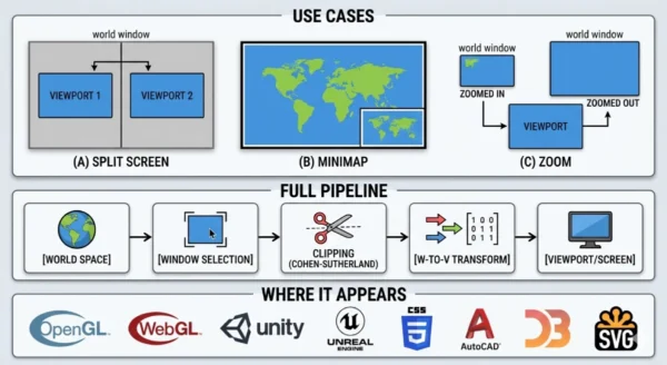
12 Critical Differences: Viewport vs Window in Computer Graphics
Aspect | Window (World Window) | Viewport |
|---|---|---|
| Coordinate space | World coordinate space — units defined by the application (metres, game units, degrees, pixels) | Screen or device coordinate space — always measured in pixels (or device-independent pixels) |
| Purpose | Selects what region of the world scene to render — the camera aperture into world space | Specifies where on the display the rendered output appears — the target region on screen |
| Effect of resizing | Resizing the window changes the field of view: smaller window = zoom in; larger window = zoom out | Resizing the viewport changes the display area: larger viewport = bigger image on screen, same world content |
| Effect of moving | Moving (translating) the window pans the camera through world space — equivalent to camera pan | Moving the viewport repositions the rendered output on screen — content unchanged, display position changes |
| Clipping boundary | Yes — the window boundary is the clipping boundary. Primitives outside the window are discarded | No separate clipping stage — clipping was performed at the window stage before viewport transformation |
| Relationship to display hardware | No direct relationship to display pixels or resolution — purely a mathematical construct in world space | Directly mapped to display hardware — bounded by the framebuffer or canvas resolution |
| Multiple instances | Multiple windows can select different regions of the same world (main view + minimap) | Multiple viewports can appear simultaneously on screen, each receiving different render output |
| OpenGL API | Set implicitly via projection matrix (glOrtho, glFrustum, gluPerspective) | Set explicitly via glViewport(x, y, width, height) |
| Units | Application-defined — could be real-world units, arbitrary game units, or normalised [-1,1] range | Pixels — integer or floating-point pixel coordinates in the rendering target |
| Aspect ratio impact | Window aspect ratio determines the shape of the selected world region | Viewport aspect ratio determines displayed output shape; mismatch between window and viewport causes distortion |
| CSS / browser equivalent | SVG viewBox; Canvas coordinate transform; no direct CSS equivalent for the world window | Browser viewport (vw, vh); @viewport; meta viewport tag; directly corresponds to CSS viewport concept |
| Zoom implementation | Zoom is implemented by changing the window: shrink for zoom-in, expand for zoom-out | Viewport stays the same during zoom — only the window changes to control what world region maps into it |
Clipping: What Happens at the Window Boundary
Clipping is the stage between window selection and viewport transformation. Its job is to ensure that only geometry lying within (or exactly on the boundary of) the window passes to the next stage. Without clipping, primitives that partially extend outside the window would be transformed into the viewport and then rendered partly outside the viewport boundaries — causing visual artefacts and potentially writing pixels outside the allocated rendering region.
Cohen-Sutherland Line Clipping
The Cohen-Sutherland algorithm clips line segments against a rectangular window boundary. It assigns each endpoint a 4-bit region code (called an outcode) indicating which of the four half-planes (left, right, bottom, top) the point lies outside of.
- Both endpoints inside: Line is trivially accepted — no clipping needed
- Both endpoints share an outside region: Line is trivially rejected — entirely outside window
- Otherwise: Compute intersection with the relevant window edge and recurse until trivially accepted or rejected
Region codes (bit positions):
  bit 0 (LEFT):   Px < Wxmin
  bit 1 (RIGHT):  Px > Wxmax
  bit 2 (BOTTOM): Py < Wymin
  bit 3 (TOP):    Py > Wymax

Trivial accept: code_A | code_B == 0000
Trivial reject: code_A & code_B != 0000
Liang-Barsky and Sutherland-Hodgman
Liang-Barsky clips lines using parametric form, expressing a line as P(t) = P1 + t(P2−P1) and computing the t values where the line intersects each window edge. It is generally faster than Cohen-Sutherland because it avoids repeated intersection calculations when multiple edges are involved.
Sutherland-Hodgman clips entire polygons against the window rectangle by processing one edge of the clipping rectangle at a time. Each pass produces a new polygon whose vertices lie on or inside that edge. After four passes (left, right, bottom, top), the result is the portion of the original polygon inside the window — potentially with new vertices inserted at the window boundary.
Modern GPU pipelines perform equivalent clipping in normalised device coordinates (NDC) after the vertex shader, but the principle is identical to the 2D window-clipping algorithms above.
Why clipping happens at the window, not the viewport:
Clipping must occur in world coordinate space (at the window boundary) rather than in screen space (at the viewport boundary) because the window-to-viewport transformation is a linear scaling. A primitive that extends far outside the window could, after transformation, map to coordinates orders of magnitude outside the viewport — producing integer overflow in pixel calculations, writing outside framebuffer memory, or creating triangles so large that rasterisation takes excessive time. Clipping at the window stage eliminates these problems before they reach the transformation step.
Real-World Applications
The window-viewport model appears in every rendering context. Understanding it by name makes many seemingly complex rendering features immediately obvious.
CAD and Technical Drawing Tools
CAD applications like AutoCAD work in real-world units (millimetres, inches, metres). The “drawing” is in world space — a circuit board layout might span 200mm × 100mm. The screen might be 1920×1080 pixels.
- Zoom in: Shrink the window — a 10mm × 5mm window fills the full 1920×1080 viewport, showing fine detail
- Zoom to extents: Set the window to encompass the entire 200mm × 100mm drawing
- Pan: Translate the window without changing its size — slides the view across the drawing
- Multiple views (paper space): Multiple viewports on a layout sheet, each showing a different window into the model space
Game Engines: Split-Screen and Minimap
Game engines implement split-screen and minimap features directly through the viewport system.
- Split-screen: Two viewports, each occupying half the screen (Viewport 1: x=0–960, y=0–1080; Viewport 2: x=960–1920, y=0–1080). Each camera defines its own world window. The engine renders the scene twice, once to each viewport
- Minimap: A small viewport in the screen corner (e.g., 200×200 pixels). Its associated camera has a wide window covering the entire game level — the small viewport displays the full-world view at tiny scale. The main camera has a narrow window around the player — the large main viewport shows close-up detail
- Rear-view mirror: A small viewport rendering a reversed camera — one additional render pass, one additional small viewport
Web Browsers and CSS
The browser viewport is the area of the browser window in which the web page is visible — exactly the viewport in the graphics sense. CSS units vw (viewport width) and vh (viewport height) directly reference its dimensions.
- SVG viewBox: The
viewBoxattribute on an SVG element defines the world-coordinate window. The SVGwidthandheightattributes define the viewport.viewBox="0 0 100 100" width="500" height="500"scales the 100×100 world-unit drawing to a 500×500 pixel viewport - CSS transforms: Scaling and translating elements in the DOM is equivalent to manipulating the viewport of each element’s coordinate space
- Meta viewport tag:
<meta name="viewport" content="width=device-width">instructs the browser to set the CSS viewport width equal to the physical device screen width — a viewport configuration instruction
OpenGL / WebGL
Modern 3D APIs implement the window concept through the projection matrix and the viewport explicitly through a dedicated function call.
- Projection matrix: The view frustum (perspective) or the orthographic box (ortho) is the 3D generalisation of the 2D window — it defines which volume of 3D world space maps to the normalised device coordinate (NDC) cube [−1,1]³
- NDC space: An intermediate step between the 3D window (clip space) and the viewport — all visible geometry lives in the [−1,1] cube after projection
- glViewport(x, y, w, h): Maps NDC space to the defined screen rectangle. This is the explicit viewport setting call — changing it is how OpenGL implements split-screen and off-screen rendering
- Framebuffer objects: Render-to-texture pipelines define a viewport into an off-screen framebuffer — the window-to-viewport mapping applies even when the “viewport” is not a physical screen
Common Patterns, Pitfalls and Design Notes
The Y-Axis Flip Problem
The most common bug arising from the window-viewport transformation is the y-axis orientation mismatch. Mathematical coordinate systems and OpenGL place the y-axis origin at the bottom-left (y increases upward). Screen coordinate systems — Windows GDI, HTML5 Canvas, CSS, most UI frameworks — place the origin at the top-left (y increases downward). When mixing these systems, a point at the top of the world window will map to the bottom of the screen viewport and vice versa. The fix is a y-flip in the viewport transformation: Vy = (Vymax - Vymin) - (Sy × (Py - Wymin)) + Vymin. Modern APIs handle this automatically, but implementing the transformation from scratch requires awareness of which convention each layer uses.
Aspect Ratio Preservation
When Sx ≠ Sy — the window and viewport have different aspect ratios — the image is distorted. Two strategies handle this:
- Letterbox / pillarbox: Set Sx = Sy = min(Sx, Sy) and adjust Vxmin/Vymin to centre the smaller scaled image within the viewport. Black bars fill the unused viewport area
- Crop: Set Sx = Sy = max(Sx, Sy) and allow the image to extend slightly beyond the viewport boundary (it will be clipped by the display hardware). Fills the viewport with no black bars but cuts off the edges of the world window
Zoom vs Viewport Resize
A common question: what is the difference between zooming in and making the viewport larger? They produce similar visual results — more pixels show the object — but the mechanism is opposite:
- Zoom in: Shrink the window. Same viewport size, fewer world units visible. The scene is magnified because the same viewport pixels represent a smaller world region
- Enlarge viewport: Keep the window the same, make the viewport bigger in pixels. More pixels display the same world region — the object appears larger because it fills more screen area, but the world window (field of view) is unchanged
Implementing a Complete 2D Viewer: Quick Reference
| Feature | What to Change | What Stays Fixed |
|---|---|---|
| Pan left | Decrease Wxmin and Wxmax by equal amount | Viewport, window size |
| Zoom in | Shrink window symmetrically around centre | Viewport |
| Zoom out | Expand window symmetrically around centre | Viewport |
| Zoom to point | Shrink window, recentre on target point | Viewport |
| Resize display area | Change viewport dimensions (Vxmax, Vymax) | Window (world view unchanged) |
| Add minimap | Add a second small viewport; set its window to full world extents | Main viewport and main window |
| Split screen | Define two viewports (left half, right half); assign separate windows/cameras | World scene |
| Fit all objects on screen | Set window to bounding box of all scene objects | Viewport |
Frequently Asked Questions
Vx = ((Px − Wxmin) / (Wxmax − Wxmin)) × (Vxmax − Vxmin) + Vxmin
Vy = ((Py − Wymin) / (Wymax − Wymin)) × (Vymax − Vymin) + Vymin
Equivalently, define scaling factors Sx = (Vxmax − Vxmin) / (Wxmax − Wxmin) and Sy = (Vymax − Vymin) / (Wymax − Wymin), then: Vx = Sx × (Px − Wxmin) + Vxmin and Vy = Sy × (Py − Wymin) + Vymin. The transformation normalises the point’s position within the window (as a fraction from 0 to 1), then applies that fraction to the viewport extent. A point at the exact centre of the window always maps to the exact centre of the viewport regardless of the absolute coordinates of either rectangle.
glViewport(x, y, width, height) sets the viewport — the rectangle of screen pixels that will receive OpenGL’s rendered output. It specifies the bottom-left corner (x, y) and dimensions (width, height) of the destination rectangle on the screen or framebuffer. In OpenGL’s pipeline, the “window” concept is embedded in the projection matrix: glOrtho(left, right, bottom, top, near, far) for orthographic projection defines the 3D viewing volume (the window in 3D), and perspective projection matrices implicitly define the viewing frustum. The vertex shader transforms geometry through model → world → view → clip space, the geometry then passes through NDC (normalised device coordinates, the [−1,1]³ cube), and finally glViewport maps the NDC cube to the specified screen rectangle. Changing glViewport between draw calls without clearing the framebuffer allows multiple scenes or cameras to be rendered into different regions of the same screen in one frame — the standard technique for split-screen, picture-in-picture, and HUD rendering in OpenGL applications.viewBox attribute defines the world-coordinate window — it specifies the (x, y, width, height) of the rectangular region in SVG’s coordinate space that should be rendered. The SVG element’s width and height attributes (or CSS dimensions) define the viewport — the pixel dimensions the SVG occupies on screen. For example, <svg viewBox="0 0 100 100" width="500" height="500"> defines a window of 100×100 SVG units mapped to a viewport of 500×500 pixels — producing a 5× scale factor. The preserveAspectRatio attribute handles the case where window and viewport have different aspect ratios, providing options equivalent to letterbox (xMidYMid meet), crop (xMidYMid slice), or stretch (none). SVG’s viewBox is one of the clearest real-world implementations of the window-viewport model available in a commonly used technology.The Verdict
The viewport vs window distinction is one of those concepts in computer graphics that, once understood clearly, makes dozens of other things suddenly obvious. Zoom is a window operation. Pan is a window operation. Split-screen is a viewport operation. Resizing the display area is a viewport operation. Every rendering system — from a raw OpenGL application to a web browser interpreting CSS — implements this same two-stage model: define what region of the world to show (window), define where on screen to show it (viewport), clip what falls outside the window, then transform the rest.
Window — Key Points:
- Defined in world coordinate space — no pixel units
- Selects which region of the scene to render
- Moving it = pan; resizing it = zoom
- Its boundary is the clipping boundary
- Set via projection matrix in OpenGL; viewBox in SVG
- Multiple windows can show different parts of the same world
Viewport — Key Points:
- Defined in screen/device coordinate space — always pixels
- Specifies where on screen the output appears
- Multiple viewports enable split-screen, minimap, PiP
- Set via glViewport() in OpenGL; width/height in SVG
- Y-axis origin varies: bottom-left (OpenGL) vs top-left (CSS, Canvas)
- Must match window aspect ratio to avoid distortion
Related Topics Worth Exploring
Horizontal vs Vertical Retrace in Graphics
The viewport you define in software must ultimately be rendered by display hardware that operates one scanline at a time, with horizontal and vertical retrace periods between lines and frames. Understanding how the physical raster scan relates to the framebuffer that receives your viewport output connects the software pipeline to the hardware reality beneath it.
Logical vs Physical Memory Addresses in OS
The window-to-viewport transformation in graphics is conceptually parallel to the logical-to-physical address mapping in operating systems — both convert from an abstract coordinate space (world coordinates / logical addresses) to a hardware-specific space (screen pixels / physical RAM locations) through a managed translation layer with defined boundaries and clipping/bounds-checking behaviour.
Raster vs Vector Graphics
The window-viewport model operates differently depending on whether your graphics system is raster-based (pixels in a framebuffer) or vector-based (mathematical shapes in world coordinates). Understanding the distinction clarifies why SVG preserves quality at any viewport size while PNG does not — and why the window-to-viewport transformation is lossless in vector systems but resolution-dependent in raster ones.
Related Topics Worth Exploring
Horizontal vs Vertical Retrace in Graphics
The viewport you define in software must ultimately be rendered by display hardware that operates one scanline at a time, with horizontal and vertical retrace periods between lines and frames. Understanding how the physical raster scan relates to the framebuffer that receives your viewport output connects the software pipeline to the hardware reality beneath it.
Windowing vs Clipping in Computer Graphics
Windowing and clipping are two sides of the same process — the window defines the visible boundary, and clipping enforces it by removing geometry that falls outside. This deep dive covers Cohen-Sutherland, Liang-Barsky, Sutherland-Hodgman, and every edge case in the battle for pixel-perfect visual precision.
Logical vs Physical Memory Addresses in OS
The window-to-viewport transformation in graphics is conceptually parallel to the logical-to-physical address mapping in operating systems — both convert from an abstract coordinate space to a hardware-specific space through a managed translation layer with defined boundaries and bounds-checking behaviour.